Friday 29 April 2016

Monday 25 April 2016
Utilization Of Geothermal Energy(Totally Innovative Idea Given By Billions in Change)
Energy straight from the core.
We can power the world with clean resources that are right under our feet.
INTRODUCTION
https://youtu.be/jD-_ACt7Q1U

THE PROBLEM
Limited Clean Energy
Burning fossil fuels and creating nuclear reactions to generate electricity comes at a high cost – politically and environmentally. Alternative methods are limited and come with tradeoffs. The answer to these problems is right under our feet.
https://youtu.be/DUfgcPwKKj4
THE SOLUTION
Our Solution: Limitless Energy
Not too far below the surface of the Earth, it’s hot. That heat can create enough clean energy to power the world, and help keep things cool above. Using cables made from graphene, a form of pure carbon 100 times stronger that steel, that heat can be conducted to the surface of the Earth to run turbines and generate electricity – without burning anything. We call it Limitless Energy.
ELECTRIC CLOTHES (UTILITY OF THERMOELECTIC GENERATOR)
The Seebeck effect is a phenomenon in which a temperature difference between two dissimilar electrical conductors or semiconductors produces a voltage difference between the two substances.


 Physicists at Wake Forest University have developed a fabric that doubles as a spare outlet. When used to line your shirt — or even your pillowcase or office chair — it converts subtle differences in temperature across the span of the clothing (say, from your cuff to your armpit) into electricity. And because the different parts of your shirt can vary by about 10 degrees, you could power up your MP3 player just by sitting still. According to the fabric’s creator, David Carroll, a cellphone case lined with the material could boost the phone’s battery charge by 10 to 15 percent over eight hours, using the heat absorbed from your pants pocket.
NOW BY THIS PHENOMENON WE CAN MAKE
Physicists at Wake Forest University have developed a fabric that doubles as a spare outlet. When used to line your shirt — or even your pillowcase or office chair — it converts subtle differences in temperature across the span of the clothing (say, from your cuff to your armpit) into electricity. And because the different parts of your shirt can vary by about 10 degrees, you could power up your MP3 player just by sitting still. According to the fabric’s creator, David Carroll, a cellphone case lined with the material could boost the phone’s battery charge by 10 to 15 percent over eight hours, using the heat absorbed from your pants pocket. Wednesday 20 April 2016
Research Suggests How Solar Panels Could Produce Electricity From Rain As Well As Sunshine
Research Suggests How Solar Panels Could Produce Electricity From Rain As Well As Sunshine
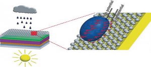
Solar energy is on the rise. Many technical advances have made solar cells quite efficient and affordable in recent years.
A big disadvantage remains in the fact that solar cells produce no power when it’s raining. This may change, however: In the journal Angewandte Chemie, Chinese researchers have now introduced a new approach for making an all-weather solar cell that is triggered by both sunlight and raindrops.
For the conversion of solar energy to electricity, the team from the Ocean University of China (Qingdao) and Yunnan Normal University (Kunming, China) developed a highly efficient dye-sensitized solar cell. In order to allow rain to produce electricity as well, they coated this cell with a whisper-thin film of graphene.
http://www.pvbuzz.com/rain-to-produce-electricity-solar-cells/
click this link to know more
Tuesday 19 April 2016
Project: 03- GO GREEN!
We in this project tried to explore new and
green energy sources to use these in our daily life applications. Here the
application demonstrated is charging the phone. Following are some of them,
Solar Power:-
Solar power is the
conversion of sunlight into electricity, either directly using
photovoltaics (PV), or indirectly using concentrated solar power (CSP). Concentrated solar power systems use lenses
or mirrors and tracking systems to focus a large area of sunlight into a small
beam.
Human mechanical power
We have made a device that can use human
power to charge a mobile phone; there may be many more utility of this.
THANK YOU
Free Electricity For 24 hours
Can be Future solution for the energy crisis .must watch the video click on the link....
https://www.youtube.com/watch?v=VQY-2F1EYSs

https://www.youtube.com/watch?v=VQY-2F1EYSs

Saturday 16 April 2016

Monday 11 April 2016
Wednesday 6 April 2016
Encrypted Data Transfer
Project: 01- Encrypted Data Transfer
Our project deals with the demonstration of modern days’ technology of transmitting data through high security encryption in commercial and military use. We have used a very simple system of Transmitter and receiver module and chipper software for the project. This project gives an outline to a layman about how the modern systems handles and secures electronic data transfers.
9796) was adopted. It is based on the RSA public-key scheme. In 1994 the U.S. Government adopted the Digital Signature Standard, a mechanism based on the ElGamal publickey scheme. The search for new public-key schemes, improvements to existing cryptographicmechanisms, and proofs of security continues at a rapid pace. Various standards and infrastructures involving cryptography are being put in place. Security products are being developed to address the security needs of an information intensive society.
The way information is recorded has not changed dramatically over time. Whereas information was typically stored and transmitted on paper, much of it now resides on magnetic media and is transmitted via telecommunications systems, some wireless. What has changed dramatically is the ability to copy and alter information. One can make thousands of identical copies of a piece of information stored electronically and each is indistinguishable from the original. With information on paper, this is much more difficult. What is needed then for a society where information is mostly stored and transmitted in electronic form is a means to ensure information security which is independent of the physical medium recording or conveying it and such that the objectives of information security rely solely on digital information itself.
Project details This project has two parts; they are the Software part and the Hardware part. While the software part is used for encrypting the message to be sent in the transmitter side and decrypting it in the receiver side of the system, the hardware part is there for transmitting and receiving the message using the Morse code. In today’s world though Morse has almost no significance but the easiest way to transmit data in this simple model can only be done using the code. We have slightly modified it according to our use as we will be having LEDs for the data transmission so the ‘Dot’ in is the blinking of the ‘Red’ LED and the ‘Dash’ is the blinking of the ‘Yellow’ LED. As we can transmit 4 bits of data simultaneously, we can use four LEDs for different purpose.
Software-
We have used two softwares for the encoding and decoding purpose which will be used in series with each other. First we will put the message in the first software and then the encoded data will be put into the second software. The result of it will be transmitted and will be decoded similarly using the same software in the receiving side. The softwares with .exe extension is available with this pdf.
Hardware-
Description This radio frequency (RF) transmission system employs Amplitude Shift Keying (ASK) with transmitter/receiver (Tx/Rx) pair operating at 434 MHz. The transmitter module takes serial input and transmits these signals through RF. The transmitted signals are received by the receiver module placed away from the source of transmission. The system allows one way communication between two nodes, namely, transmission and reception. The RF module has been used in conjunction with a set of four channel encoder/decoder ICs. Here HT12E & HT12D have been used as encoder and decoder respectively. The encoder converts the parallel inputs (from the remote switches) into serial set of signals. These signals are serially transferred through RF to the reception point. The decoder is used after the RF receiver to decode the serial format and retrieve the original signals as outputs. These outputs can be observed on corresponding LEDs.
Encoder IC (HT12E) receives parallel data in the form of address bits and control bits. The control signals from remote switches along with 8 address bits constitute a set of 12 parallel signals. The encoder HT12E encodes these parallel signals into serial bits.
Transmission is enabled by providing ground to pin14 which is active low. The control signals are given at pins 10-13 of HT12E. The serial data is fed to the RF transmitter through pin17 of HT12E.
Transmitter, upon receiving serial data from encoder IC (HT12E), transmits it wirelessly to the RF receiver. The receiver, upon receiving these signals, sends them to the decoder IC (HT12D) through pin2. The serial data is received at the data pin (DIN, pin14) of HT12D. The decoder then retrieves the original parallel format from the received serial data.
When no signal is received at data pin of HT12D, it remains in standby mode and consumes very less current (less than 1μA) for a voltage of 5V. When signal is received by receiver, it is given to DIN pin (pin14) of HT12D. On reception of signal, oscillator of HT12D gets activated. IC HT12D then decodes the serial data and checks the address bits three times. If these bits match with the local address pins (pins 1-8) of HT12D, then it puts the data bits on its data pins (pins 10-13) and makes the VT pin high. An LED is connected to VT pin (pin17) of the decoder. This LED works as an indicator to indicate a valid transmission. The corresponding output is thus generated at the data pins of decoder IC. A signal is sent by lowering any or all the pins 10-13 of HT12E and corresponding signal is received at receiver’s end (at HT12D). Address bits are configured by using the by using the first 8 pins of both encoder and decoder ICs. To send a particular signal, address bits must be same at encoder and decoder ICs. By configuring the address bits properly, a single RF transmitter can also be used to control different RF receivers of same frequency. To summarize, on each transmission, 12 bits of data is transmitted consisting of 8 address bits and 4 data bits. The signal is received at receiver’s end which is then fed into decoder IC. If address bits get matched, decoder converts it into parallel data and the corresponding data bits get lowered which could be then used to drive the LEDs. The outputs from this system can either be used in negative logic or NOT gates (like 74LS04) can be incorporated at data pins.
COMPONENTS USED 1. HT12D DECODER
HT12D IC comes from HolTek Company. HT12D is a decoder integrated circuit that belongs to 212 series of decoders. This series of decoders are mainly used for remote control system applications, like burglar alarm, car door controller, security system etc. It is mainly provided to interface RF and infrared circuits. They are paired with 212 series of encoders. The chosen pair of encoder/decoder should have same number of addresses and data format. In simple terms, HT12D converts the serial input into parallel outputs. It decodes the serial addresses and data received by, say, an RF receiver, into parallel data and sends them to output data pins. The serial input data is compared with the local addresses three times continuously. The input data code is decoded when no error or unmatched codes are found. A valid transmission in indicated by a high signal at VT pin. HT12D is capable of decoding 12 bits, of which 8 are address bits and 4 are data bits. The data on 4 bit latch type output pins remain unchanged until new is received.
Pin Diagram
Pin Description
Pin Number
Function
Name
1 8 BIT ADDRESS PINS FOR INPUT
A0
2 A1 3 A2 4 A3 5 A4 6 A5 7 A6 8 A7 9 GROUND (0V) GROUND 10 4 BIT DATA/ADDRESS PINS FOR OUTPUT D0 11 D1 12 D2 13 D3 14 SERIAL DATA INPUT INPUT 15 OSCILLATOR OUTPUT OSC 2 16 OSCILLATOR INPUT OSC 1 17 VALID TRANSMISSION, ACTIVE HIGH VT 18 SUPPLY VOLTAGE; 5V (2.4 – 12V) Vcc
2. HT12E ENCODER
HT12E is an encoder integrated circuit of 212 series of encoders. They are paired with 212 series of decoders for use in remote control system applications. It is mainly used in interfacing RF and infrared circuits. The chosen pair of encoder/decoder should have same number of addresses and data format. Simply put, HT12E converts the parallel inputs into serial output. It encodes the 12 bit parallel data into serial for transmission through an RF transmitter. These 12 bits are divided into 8 address bits and 4 data bits. HT12E has a transmission enable pin which is active low. When a trigger signal is received on TE pin, the programmed addresses/data are transmitted together with the header bits via an RF or an infrared transmission medium. HT12E begins a 4-word transmission cycle upon receipt of a transmission enable. This cycle is repeated as long as TE is kept low. As soon as TE returns to high, the encoder output completes its final cycle and then stops.
Pin Diagram
Pin Description
Pin Number
Function
Name
1 8 BIT ADDRESS PINS FOR INPUT
A0
2 A1 3 A2 4 A3 5 A4 6 A5 7 A6 8 A7 9 GROUND (0V) GROUND 10 4 BIT DATA/ADDRESS PINS FOR INPUT D0 11 D1 12 D2 13 D3 14 TRANSMISSION ENABLE (ACTIVE LOW) TE 15 OSCILLATOR OUTPUT OSC 2 16 OSCILLATOR INPUT OSC 1 17 VALID TRANSMISSION, ACTIVE HIGH VT 18 SUPPLY VOLTAGE; 5V (2.4 – 12V) Vcc
3. RF MODULES (434MHz)
The RF module, as the name suggests, operates at Radio Frequency. The corresponding frequency range varies between 30 kHz & 300 GHz. In this RF system, the digital data is represented as variations in the amplitude of carrier wave. This kind of modulation is known as Amplitude Shift Keying (ASK). Transmission through RF is better than IR (infrared) because of many reasons. Firstly, signals through RF can travel through larger distances making it suitable for long range applications. Also, while IR mostly operates in line-of-sight mode, RF signals can travel even when there is an obstruction between transmitter & receiver. Next, RF transmission is more strong and reliable than IR transmission. RF communication uses a specific frequency unlike IR signals which are affected by other IR emitting sources. This RF module comprises of an RF Transmitter and an RF Receiver. The transmitter/receiver (Tx/Rx) pair operates at a frequency of 434 MHz. An RF transmitter receives serial data and transmits it wirelessly through RF through its antenna connected at pin4. The transmission occurs at the rate of 1Kbps - 10Kbps.The transmitted data is received by an RF receiver operating at the same frequency as that of the transmitter.
The RF module is often used along with a pair of encoder/decoder. The encoder is used for encoding parallel data for transmission feed while reception is decoded by a decoder. HT12E-HT12D, HT640-HT648, etc. are some commonly used encoder/decoder pair ICs.
Pin Diagram Receiver Module
Transmitter Module
Transmitter Module
Pin Number
Function
Name 1 Ground (0V) GND 2 Serial Data Input Pin DATA 3 Supply Voltage (5V) VCC 4 Antenna Output Pin ANT
Receiver Module
Pin Number
Function
Name 1 Ground (0V) GND 2 Serial Data Output Pin DATA 3 Linear Output Pin; Not Connected NC 4 Supply Voltage (5V) VCC 5 Supply Voltage (5V) VCC 6 Ground (0V) GND 7 Ground (0V) GND 8 Antenna Input Pin ANT
Stills-
THANK YOU
For more information please go to our facebook page https://www.facebook.com/madforinnovation/
Or subscribe us at youtube https://www.youtube.com/channel/UChCFjx2EEMRlgRLcRUgljyg https://www.youtube.com/watch?v=yRC-J9_NoZE
Subscribe to:
Posts (Atom)