Thursday 7 July 2016


Monday 4 July 2016


Saturday 2 July 2016
Inside a dry cell battery

 A battery contains electrochemical cells that can store chemical energy to be converted to electrical energy. Adry-cell battery stores energy in an immobilized electrolyte paste, which minimizes the need for water. Common examples of dry-cell batteries include zinc-carbon batteries and alkaline batteries.

Construction of the Fluorescent Lamp
A fluorescent lamp or a fluorescent tube is a low pressure mercury-vapor gas-discharge lamp that uses fluorescenceto produce visible light. An electric current in the gas excites mercury vapor which produces short-wave ultraviolet lightthat then causes a phosphor coating on the inside of thelamp to glow.


Explaining Different Types of Transformers
A transformer is an electrical device which, by the principles of electromagnetic induction,
transfers electrical energy from one electric circuit to another, without changing the frequency.
The energy transfer usually takes place with a change of voltage and current. Transformers
either increases or decreases AC voltage.
Transformers are used to meet a wide variety of needs. Some transformers can be several
stories high, like the type found at a generating station or small enough to hold in your hand,
which might be used with the charging cradle for a video camera. No matter what the shape
or size, a transformers purpose remains the same: transforming electrical power from one
type to another.
There are many different types of transformers in use today. This resource will take a closer
look at Power Transformers, Auto Transformers, Distribution Transformers, Instrument
Transformers, Isolation Transformers, Potential Transformers and Current Transformers.
How Transformers Work
It is important to remember that transformers do not generate electrical power; they transferelectrical power from one AC circuit to another using magnetic coupling. The core of the
transformer is used to provide a controlled path for the magnetic flux generated in the
transformer by the current flowing through the windings, which are also known as coils.
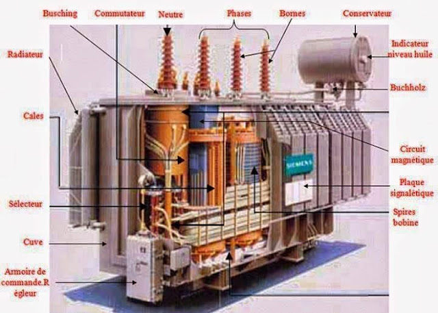
There are four primary parts to the basic transformer. The parts include the Input
Connection, the Output Connection, the Windings or Coils and the Core.

- Input Connections - The input side of a transformer is called the primary side
- because the main electrical power to be changed is connected at this point.
- Output Connections - The output side or secondary side of the transformer is
- where the electrical power is sent to the load. Depending on the requirement of
- the load, the incoming electric power is either increased or decreased.
- Winding - Transformers have two windings, being the primary winding and the
- secondary winding. The primary winding is the coil that draws power from the source.
- The secondary winding is the coil that delivers the energy at the transformed or
- changed voltage to the load. Usually, these two coils are subdivided into several coils in
- order to reduce the creation of flux.
- Core - The transformer core is used to provide a controlled path for the magnetic flux
- generated in the transformer. The core is generally not a solid bar of steel, rather a
- construction of many thin laminated steel sheets or layers. This construction is used to
- help eliminate and reduce heating.
Transformers generally have one of two types of cores: Core Type and Shell Type. - These two types are distinguished from each other by the manner in which the primary
- and secondary coils are place around the steel core.
- Core type - With this type, the windings surround the laminated core.
- Shell type - With this type, the windings are surrounded by the laminated core.
the primary winding. As the current flows, a changing magnetic field is set up in the
transformer core. As this magnetic field cuts across the secondary winding, alternating
voltage is produced in the secondary winding.
The ratio between the number of actual turns of wire in each coil is the key in determining
the type of transformer and what the output voltage will be. The ratio between output
voltage and input voltage is the same as the ratio of the number of turns between the two
windings.
A transformers output voltage is greater than the input voltage if the secondary winding has
more turns of wire than the primary winding. The output voltage is stepped up, and
considered to be a "step-up transformer". If the secondary winding has fewer turns than
the primary winding, the output voltage is lower. This is a "step-down transformer".

Transformer Configurations
There are different configurations for both single-phase and three-phase systems.- Single-phase Power - Single-phase transformers are often used to supply power for
- residential lighting, receptacle, air-conditioning, and heating needs. Single phase
- transformers can be made even more versatile by having both the primary winding
- and secondary winding made in two equal parts. The two parts of either winding can
- then be reconnected in series or parallel configurations.
- Three-phase Power - Power may be supplied through a three-phase circuit containing
- transformers in which a set of three single-phase transformers is used, or on three-
- phase transformer is used. When a considerable amount of power is involved in the
- transformation of three-phase power, it is more economical to use a three-phase
- transformer. The unique arrangement of the windings and core saves a lot of iron.
- Delta and Wye Defined - There are two connection configurations for three-phase
- power: Delta and Wye. Delta and Wye are Greek letters that represent the way the
- conductors on the transformers are configured. In a delta connection, the three
- conductors are connected end to end in a triangle or delta shape. For a wye, all the
- conductors radiate from the center, meaning they are connected at one common point.
- Three-phase Transformers - Three-phase transformers have six windings; three
- primary and three secondary. The six windings are connected by the manufacturer
- as either delta or wye. As previously stated, the primary windings and secondary
- windings may each be connected in a delta or wye configuration. They do not have
- to be connected in the same configuration in the same transformer. The actual
- connection configurations used depend upon the application.
Power Transformer
A power transformer is used primarily to couple electrical energy from a power supply line toa circuit system, or to one or more components of the system. A power transformer used with
solid state circuits is called a rectifier transformer. A power transformer's rating is given in
terms of the secondary's maximum voltage and current-delivering capacity.
Distribution Transformer
A pole-type distribution transformer is used to supply relatively small amounts of power toresidences. It is used at the end of the electrical utility's delivery system.
Autotransformer
The autotransformer is a special type of power transformer. It consists of a single, continuouswinding that is tapped on one side to provide either a step-up or a step-down function. This
is different from a conventional two-winding transformer, which has the primary and
secondary completely isolated from each other, but magnetically linked by a common core.
The autotransformer's windings are both electrically and magnetically interconnected.
An autotransformer is initially cheaper than a similarly-rated two-winding transformer. It also
has better regulation (smaller voltage drops), and greater efficiency. Furthermore, it can be
used to obtain the neutral wire of a three-wire 240/120-volt service, just like the secondary
of a two0winding transformer. The autotransformer is considered unsafe for use on ordinary
distribution circuits. This is because the high-voltage primary circuits are connected directly
to the low-voltage secondary circuit.


Isolation Transformer
An isolation transformer is a very unique transformer. It has a 1:1 turn's ratio. Therefore, itdoes not step voltage up or down. Instead, it serves as a safety device. It is used to isolate
the grounded conductor of a power line from the chassis or any portion of a circuit load.
Using an isolation transformer does not reduce the danger or shock if contact is made across
the transformer's secondary winding.
Technically, any true transformer, whether used to transfer signals or power, is isolating, as
the primary and secondary are not connected by conductors but only by induction. However,
only transformers whose primary purpose is to isolate circuits (opposed to the more common
transformer function of voltage conversion), are routinely described as isolation transformers.
Instrument Transformer
For measuring high values of current or voltage, it is desirable to use standard low-rangemeasuring instruments together with specially-constructed instrument transformers, also called
accurate ratio transformers. An accurate ratio transformer does just as the name suggests.
It transforms at an accurate ratio to allow an attached instrument to gauge the current or
voltage without actually running full power through the instrument. It is required to transform
relatively small amounts of power because it's only load, called a burden, is the delicate moving
elements of an ammeter, voltmeter or wattmeter.
There are two types of instrument transformers:
- Current - Used with an ammeter to measure current in AC voltages
- Potential - Used with a voltmeter to measure voltage (potential difference) in AC.
Current Transformer
A current transformer has a primary coil of one or more turns of heavy wire. It is alwaysconnected in series in the circuit in which current is to be measured. The secondary coil is made
up of many turns of fine wire, which must always be connected across the ammeter terminals.
The secondary of a current transformer must never be open-circuited. This is because the
primary is not connected to a constant source. There is a wide range of possible primary
voltages, because the device can be connected to many types of conductors. The secondary
must always be available (closed-circuited) to react with the primary, to prevent the core from
becoming completely magnetized. If this happens, the instruments will no longer read
accurately.
A clamp-on ammeter works in a similar way. By opening the clamp and placing it around a
current carrying conductor, the conductor itself acts as a single turn primary. The secondary
and the ammeter are conveniently mounted in the handle of the device. The dial allows a
number of current ranges to be gauged accurately.
 Current Transformers are a type of instrument transformers. They are used for the measurement of electric currents.
Potential Transformer
A potential transformer is a carefully designed, extremely accurate step-down transformer. It isnormally used with a standard 120-volt voltmeter. By multiplying the reading on the voltmeter
(called the deflections) by the ratio of transformation, the user can determine the voltage on
the high side. Common transformation ratios are 10:1, 20:1, 40:1, 80:1, 100:1, 120:1, and
even higher.
In general, a potential transformer is very similar to a standard two-winding transformer,
except that it handles a very small amount of power. Transformers for this service are always
the shell type, because this construction has been proven to provide better accuracy.

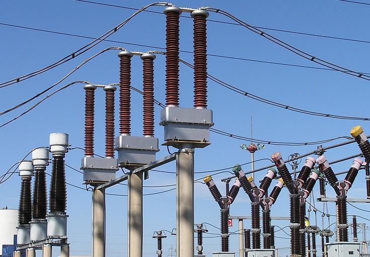
Potential Transformers (like the one pictured above) are designed for monitoring single-phase
and three-phase power line voltages in power metering applications.
Types of Transformers
Transformers generally have one of two types of cores:
1)Core Type and ,
2)Shell Type.
These two types are distinguished from each other by the manner in which the primary and secondary coils are place around the steel core.
1)Core Type and ,
2)Shell Type.
These two types are distinguished from each other by the manner in which the primary and secondary coils are place around the steel core.
- Core type - With this type, the windings surround the laminated core.
- Shell type - With this type, the windings are surrounded by the laminated core.


Tesla Coil
A Tesla coil is an electrical resonant transformer circuit invented by Nikola Tesla around 1891. It is used to produce high-voltage, low-current, high frequency alternating-current electricity. Tesla experimented with a number of different configurations consisting of two, or sometimes three, coupled resonant electric circuits.
Tesla used these coils to conduct innovative experiments in electrical lighting, phosphorescence, X-ray generation, high frequencyalternating current phenomena, electrotherapy, and the transmission of electrical energy without wires. Tesla coil circuits were used commercially in sparkgap radio transmitters for wireless telegraphy until the 1920s and in medical equipment such aselectrotherapy and violet ray devices. Today their main use is for entertainment and educational displays, although small coils are still used today as leak detectors for high vacuum systems.


Friday 1 July 2016


Subscribe to:
Posts (Atom)